TECHNICAL ARTICLES Example 10
1. Overview and Objectives
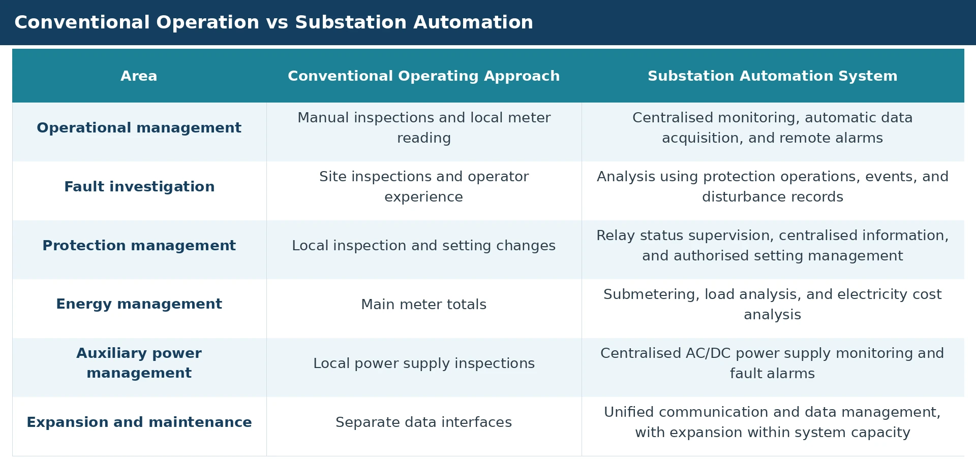
- An 11 kV / 0.4 kV substation is an important part of the power distribution infrastructure serving industrial facilities, commercial buildings, and public facilities. Its primary functions are to receive power, step down the voltage, and distribute electricity. Power is supplied from the upstream 11 kV network and transformed to 0.4 kV for distribution to low-voltage loads.
-
This solution combines the GoWatron GWSC-SUB Substation Automation &
SCADA System
, GWPR200 Series
Protection Relays
, GWPC-RTU Remote Terminal Unit Panel, GWPS Series
AC/DC Power Supply
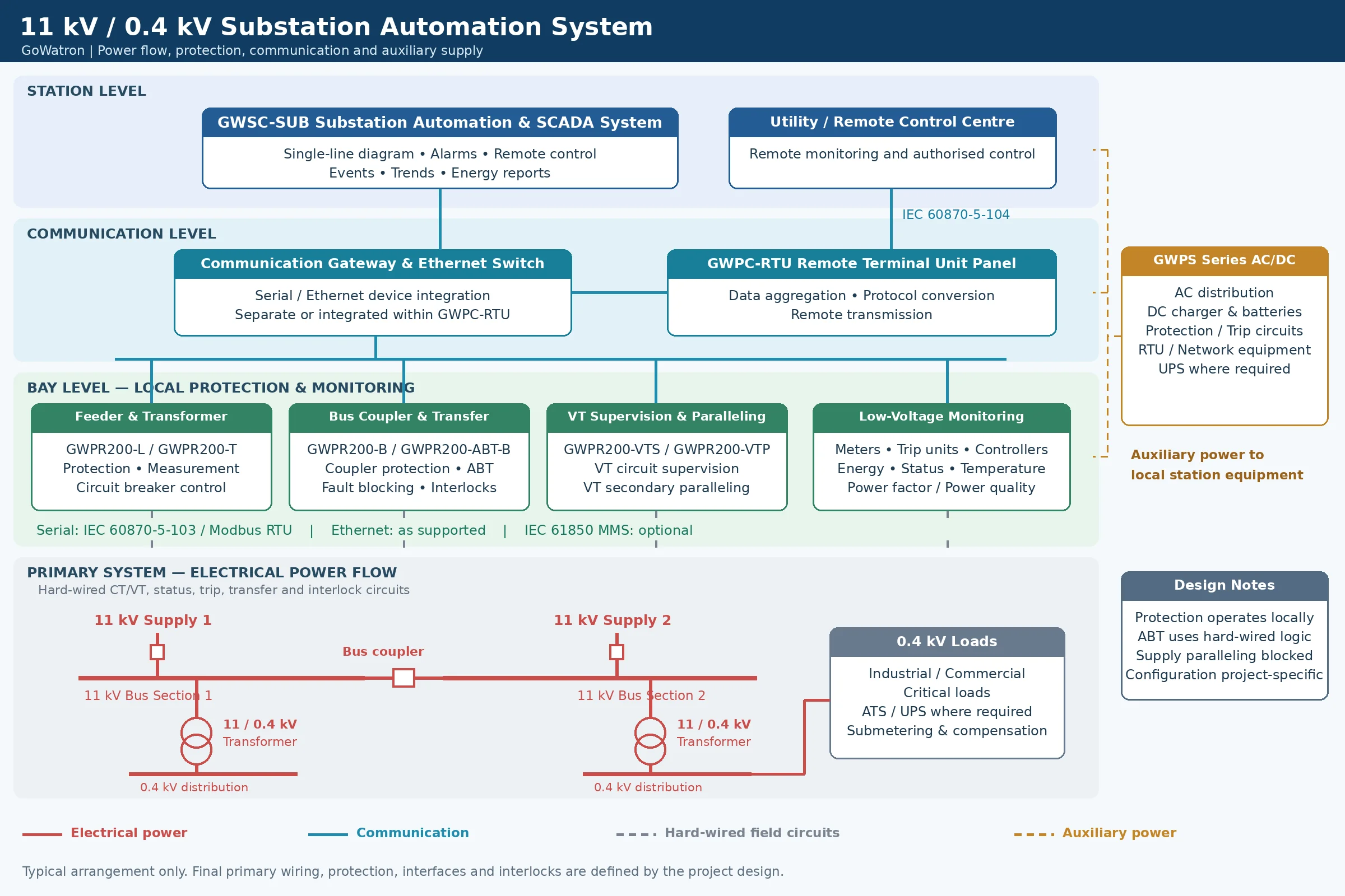
Equipment, and intelligent low-voltage meters. It adopts a distributed architecture comprising the bay level, communication level, and station level, integrating protection, equipment monitoring, communication management, and energy metering. -
Protection relays independently detect faults and initiate local tripping. The GWSC-SUB system provides centralised monitoring, supervisory control, and data management. The
GWPC-RTU panel
aggregates data and transmits it to remote systems, while GWPS Series power supply equipment provides reliable auxiliary power for protection, control, communication, and monitoring equipment.
The main objectives are:
-
Reliable power supply: Isolate faults rapidly and selectively through appropriate protection arrangements and coordination.
Centralised monitoring: Provide real-time visibility of equipment status, reduce manual meter reading and local operating work, and support unattended operation. -
Energy management: Collect circuit-level energy data to support load analysis, cost allocation, and energy efficiency management.
Safe operation: Reduce operating errors and unauthorised access through mechanical interlocks, electrical interlocks, access permissions, and cybersecurity measures. - Flexible expansion: Select equipment and network configurations according to project size and supply criticality, allowing additional circuits and monitoring functions to be incorporated.
2. System Architecture and Equipment Configuration
2.1 Bay Level: Local Protection, Measurement, and Control
The bay level interfaces directly with circuit breakers, current transformers (CTs), voltage transformers (VTs; also known as potential transformers, PTs), and other field equipment. It provides protection, measurement, status acquisition, and local control.
GWPR200 Series protection relays are selected according to the bay application. Protection functions operate independently of the station computer and communication network. If communication is interrupted, the relays can continue to initiate tripping through local hard-wired trip circuits.
Typical 11 kV equipment configuration:
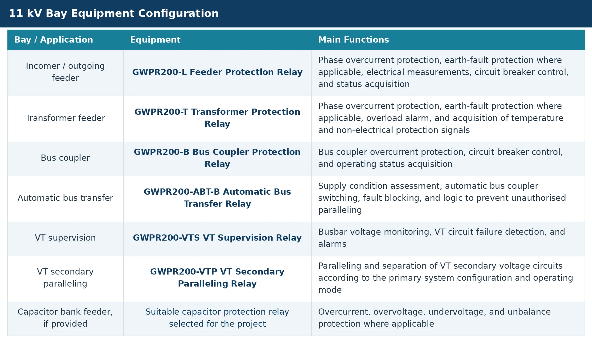
Protection functions, binary input and output quantities, measurement performance, and communication interfaces depend on the selected relay configuration.
Typical 0.4 kV equipment configuration:
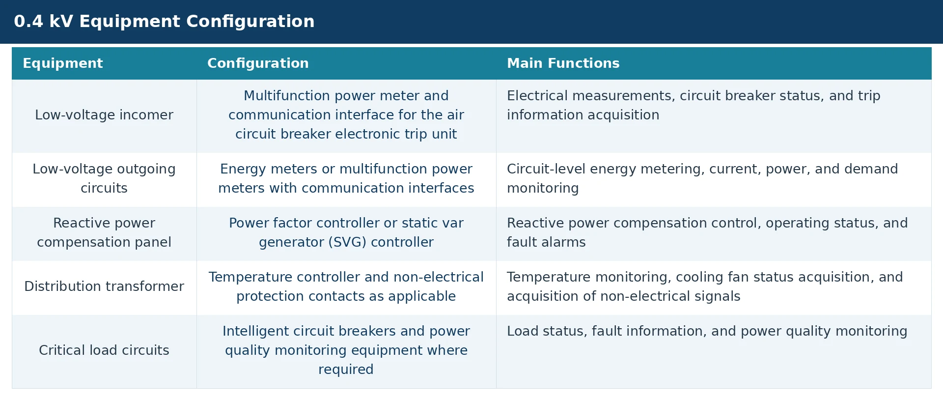
Distribution transformers are key assets requiring protection in this solution. Protection arrangements are determined by transformer type, rating, system earthing, and load criticality.
2.2 Communication Level: Data Acquisition and Remote Transmission
The communication level connects field equipment to the GWSC-SUB system and provides data acquisition, protocol conversion, and remote data transmission.
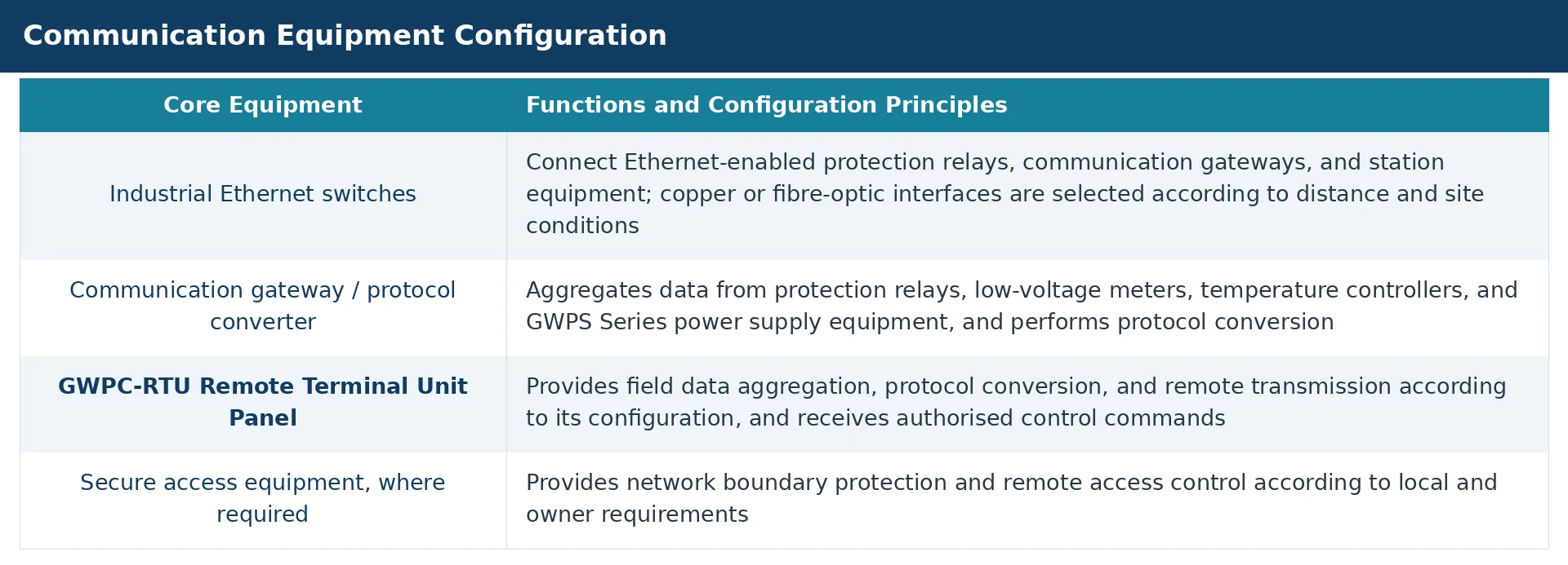
For small substations, a communication gateway may handle both local data acquisition and remote transmission. A GWPC-RTU panel can be provided where a dedicated utility interface or centralised panel arrangement is required, or where a large number of devices is involved. Communication, networking, and auxiliary equipment within the panel are configured to suit the project.
Recommended communication protocol arrangements:
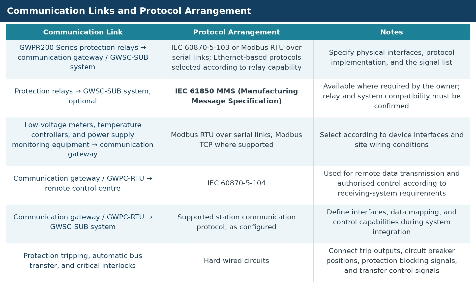
- IEC 61850 MMS is an optional configuration. Where selected, it provides station-bus communication between compatible protection relays and the station-level system. Serial communication may be retained or replaced according to device capabilities and the project design. Equipment interfaces, data models, and system integration requirements must be defined.
- Serial communication and Ethernet communication must be specified separately. Where IEC 60870-5-103 data is transported over Ethernet using manufacturer-specific encapsulation or mapping, the transport method and interoperability requirements must be confirmed.
- The communication network may use a single or redundant configuration. For a redundant network, the supported redundancy mechanism, network topology, and recovery performance must be specified, and system compatibility verified. Two Ethernet ports alone do not establish seamless redundancy.
3. Protection and Automatic Bus Transfer
3.1 11 kV Incomer and Feeder Protection
- The GWPR200-L Feeder Protection Relay is used for 11 kV incomers and outgoing feeders. Protection functions are selected according to the supply arrangement, system earthing, and utility requirements.
Typical functions include:
- Phase overcurrent protection (ANSI 50/51): Instantaneous, definite-time, or inverse-time elements, coordinated with downstream and upstream protection.
- Earth-fault protection (ANSI 50N/51N or 50G/51G): Selected according to neutral earthing, the residual or earth-current measurement arrangement, and relay capability. Directional earth-fault protection is used where a directional criterion is required.
-
Overload alarm: Indicates that feeder loading exceeds the configured threshold; the operating criterion depends on relay functionality.
Undervoltage protection (ANSI 27), where required: Used for alarm, control, or protection, with appropriate blocking for VT circuit failure. - Circuit breaker control and status supervision: Acquires open/closed positions, control circuit status, and relay failure indications.
Incomer protection must coordinate with transformer feeder protection, bus coupler protection, and upstream network protection to avoid unnecessary loss of supply to the entire substation following a downstream fault.
3.2 Distribution Transformer Protection
The
GWPR200-T Transformer Protection Relay
is used for distribution transformer feeders. Typical arrangements include phase overcurrent protection, earth-fault protection where applicable, overload alarms, and acquisition of temperature and non-electrical protection signals.
Electrical protection configuration:
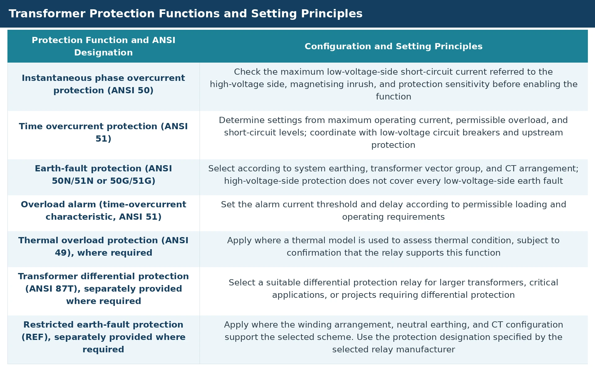
The overload alarm designation must reflect its actual operating principle. ANSI 51 applies when the alarm uses a time-overcurrent characteristic; ANSI 49 applies when the function uses a thermal model.
Restricted earth-fault protection designations vary between relay manufacturers. Project documentation must consistently use the designation specified for the selected relay.
Temperature and non-electrical protection configuration:

- Dry-type transformers typically provide winding high-temperature alarm, overtemperature trip, and cooling fan status signals. Oil-immersed transformers may provide temperature, Buchholz, pressure, and oil level signals according to their construction and fitted accessories.
-
These functions are project options. They are not all included as standard in every transformer or GWPR200-T configuration.
Non-electrical protection signals originate from transformer-mounted accessories or temperature monitoring equipment. The GWPR200-T acquires contact signals and performs the associated logic according to its configuration. Trip circuits are defined and verified as part of the project design. - Protection settings must be established through short-circuit calculations and protection coordination studies. Fixed multiples of rated current are not applied universally. An instantaneous setting does not mean zero fault-clearing time: total clearing time also includes relay operation, output operation, and circuit breaker interruption.
3.3 Bus Coupler Protection
The GWPR200-B Bus Coupler Protection Relay provides bus coupler overcurrent protection (ANSI 50/51), measurement, circuit breaker control, and operating status acquisition.
Settings are determined by the busbar sectionalisation arrangement, supply operating modes, and upstream and downstream protection. Where required, relevant protection operation signals are hard-wired to the GWPR200-ABT-B
automatic bus transfer relay
to block transfer.
Bus coupler overcurrent protection and
busbar differential protection
have different operating principles and protection coverage. A suitable separate relay must be provided where busbar
differential protection
is required.
3.4 Earth-Fault Protection
Earth-fault protection is designed for the actual system earthing arrangement:
- Low-resistance-earthed systems: Residual or earth overcurrent protection (ANSI 50N/51N or 50G/51G) may be used, with directional earth-fault protection (ANSI 67N/67G) where required.
- Unearthed or resonant-earthed systems: Use a suitable earth-fault detection or faulty-feeder identification scheme for the system conditions. Conventional residual overcurrent protection alone may be insufficient.
- 0.4 kV systems: Provide appropriate earth-fault protection, residual-current protection, or insulation monitoring according to the TN, TT, or IT earthing arrangement.
Relay current inputs, measurement sensitivity, and protection functions must suit the selected scheme. The installation position, wiring, and measurement range of core-balance current transformers (CBCTs) must be consistent with the protection design.
3.5 VT Supervision and Secondary Paralleling
The GWPR200-VTS VT Supervision Relay provides busbar voltage monitoring, VT circuit failure detection, and alarms. It supplies information for operational monitoring and associated voltage-based logic. Signals required to block protection or automatic transfer are hard-wired to the relevant relays as specified in the design.
The GWPR200-VTP VT Secondary Paralleling Relay is provided for sectionalised busbar systems requiring VT secondary voltage paralleling. Its paralleling and separation logic is designed using bus coupler circuit breaker positions, relevant disconnector positions, and VT circuit conditions.
The arrangement must:
- Permit secondary paralleling only when the primary operating arrangement and interlocking conditions allow it.
- Separate the secondary voltage circuits when the busbar sections are separated or other enabling conditions are no longer satisfied.
- Prevent back-feeding through VT secondary circuits into de-energised equipment or equipment under maintenance.
- Verify secondary circuit protection, burden, and wiring compatibility.
- VT supervision and VT secondary paralleling perform separate monitoring and control functions and are configured according to project requirements.
3.6 Automatic Bus Transfer (ABT)
The GWPR200-ABT-B Automatic Bus Transfer Relay is used for applicable dual-supply, sectionalised single-busbar arrangements. It acquires working and standby supply voltages, circuit breaker positions, and protection blocking signals through hard-wired circuits, and initiates transfer when the required conditions are satisfied.
Typical operating conditions include:
- The working supply loss criterion is satisfied, and VT circuit failure has been excluded.
- Standby supply voltage is healthy, and the supply is available to accept the transferred load.
- The original working supply circuit breaker has opened.
- No relevant fault protection, busbar fault, or maintenance blocking condition is present.
- Interlocking conditions prevent unauthorised paralleling of supplies.
- The transferred load remains within the permissible capacity of the standby supply and transformers.
Automatic transfer normally operates once per initiating event. An incomer circuit breaker trip alone is insufficient to permit transfer; loss of supply must be distinguished from tripping caused by a fault.
For systems with significant motor loads, residual voltage, motor re-acceleration current, and transfer timing must also be assessed. A dedicated transfer strategy may be required.
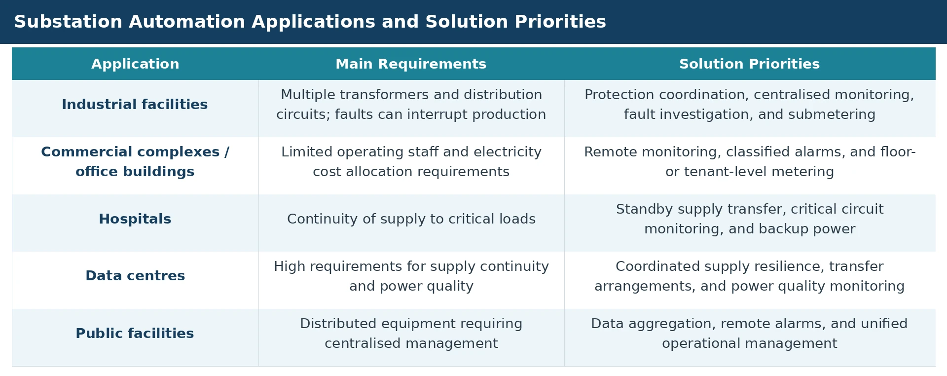
For critical facilities such as hospitals and data centres, 11 kV automatic bus transfer, 0.4 kV automatic transfer switches (ATS), and uninterruptible power supplies (UPS) must be designed and coordinated as separate parts of the overall supply continuity arrangement.
4. Monitoring and Operational Management
4.1 Real-Time Monitoring and Remote Control
The GWSC-SUB system displays substation operating conditions on a single-line diagram and provides the following functions according to the project configuration:
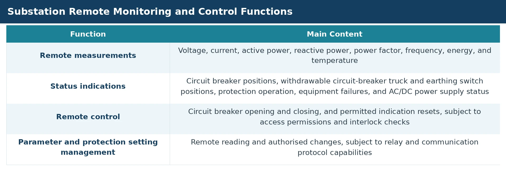
Remote opening and closing of low-voltage circuit breakers require motor-operated mechanisms, control interfaces, and reliable position feedback. Circuit breakers with communication interfaces only are integrated according to their actual monitoring and control capabilities.
4.2 Alarms, Events, and Disturbance Records
-
The system provides classified alarms for protection operation, equipment failures, excessive temperature, AC/
DC power supply
faults, and communication loss. Historical records support event review and fault investigation. - Critical events are time-stamped at source by protection relays or acquisition devices. A common time synchronisation arrangement is provided throughout the substation.
- Sequence of events (SOE) time resolution, time-stamp accuracy, and synchronisation error must be specified separately. Where a time resolution of 1 ms or better is required, compliance must be confirmed through equipment capability and acceptance testing. Performance for polled low-voltage devices is defined according to their actual acquisition characteristics.
- Protection relays with disturbance recording functions can provide fault current, voltage, and protection operation information. Where supported, records can be exported in COMTRADE (Common Format for Transient Data Exchange for Power Systems) format in accordance with IEEE C37.111 / IEC 60255-24, and retrieved through the monitoring system.
4.3 Reactive Power Compensation and Power Factor Control
- Local power factor controllers or SVG controllers manage reactive power compensation on the 0.4 kV side. The GWSC-SUB system monitors operation and provides authorised parameter management.
- Control strategies should include overvoltage and undervoltage blocking, switching delays, prevention of excessive switching, and equipment fault blocking. Where substantial harmonic loads are present, capacitor, reactor, or SVG suitability must be assessed to avoid resonance and equipment overload.
- Reactive power compensation improves power factor and may assist voltage performance. Conventional transformers with off-circuit tap changers require de-energisation for tap adjustment and cannot automatically change their transformation ratio online through SCADA.
4.4 Operating Interlocks and Switching Safety
The solution combines
switchgear
mechanical interlocks, electrical interlocks, and supervisory operating condition checks. Critical interlocks are implemented locally. The GWSC-SUB system provides access permissions, operating condition prompts, and operation records.
Applicable measures depend on equipment construction and include preventing:
- Operation of a disconnector under load.
- Closing of an earthing switch onto an energised circuit.
- Energisation of an earthed circuit.
- Unauthorised access to energised compartments.
Required switchgear mechanical interlocks and local electrical interlocks are implemented independently of the monitoring software.
4.5 Energy Management and Power Quality Monitoring
- Low-voltage submetering is arranged by workshop, floor, tenant, or equipment category. It supports energy trends, demand analysis, time-of-use electricity cost analysis, and power factor analysis, providing a basis for cost allocation and energy efficiency management. Cost calculations are configured according to local tariffs and billing rules.
- Standard multifunction meters provide basic electrical quantities and supported harmonic measurements. Dedicated power quality analysers are used where voltage dips, swells, flicker, or more comprehensive power quality analysis is required. They are integrated into GWSC-SUB according to supported interfaces.
5. GWPS Series AC/DC Power Supplies and Cybersecurity
5.1 AC/DC Auxiliary Power Supplies
GWPS Series AC/DC Power Supply Equipment provides auxiliary power to protection relays, circuit breaker operating circuits, the GWPC-RTU panel, network equipment, and monitoring computers.
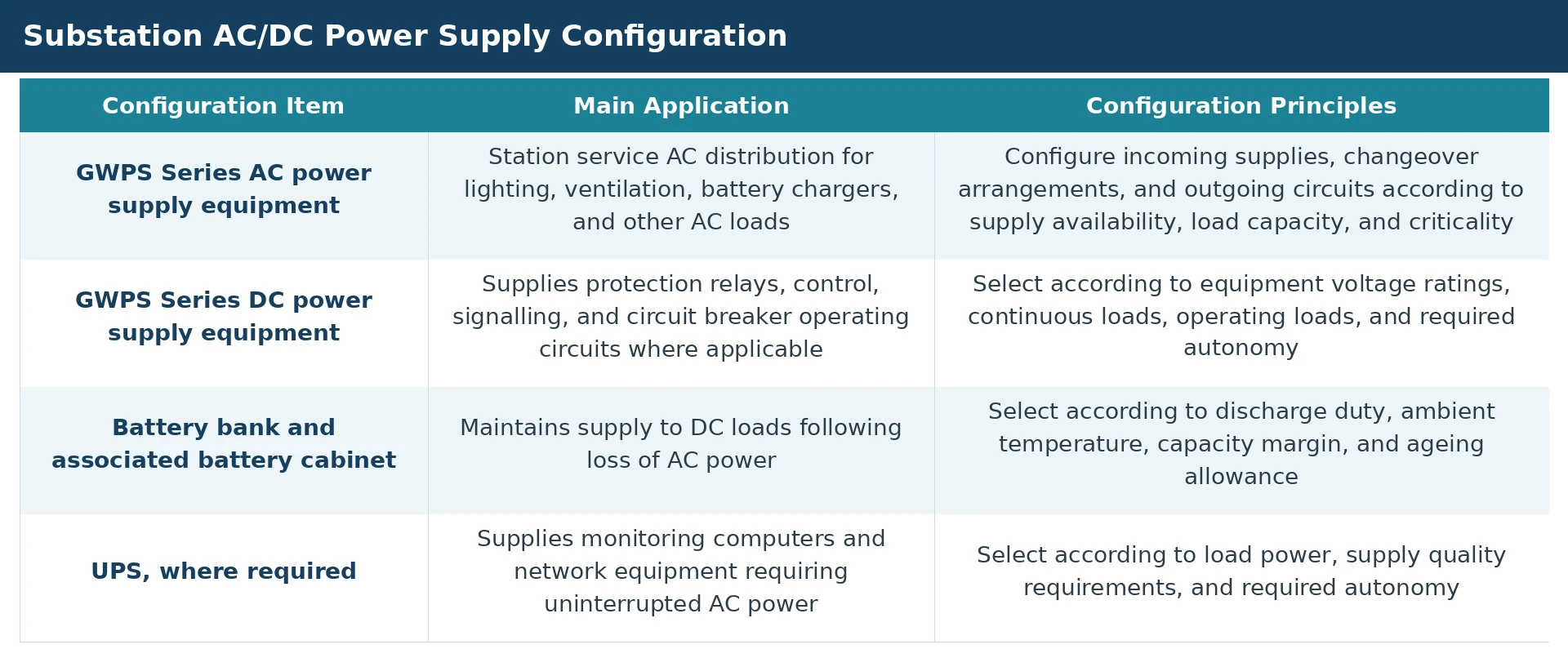
- Circuit breaker operating supplies are selected to suit the mechanism requirements. Where a DC system is used, battery terminal voltage and short-duration current capability must be checked under the specified operating conditions to ensure reliable circuit breaker operation.
- Monitoring data from GWPS Series power supply equipment is integrated into GWSC-SUB according to the selected configuration. The system monitors AC inputs, DC bus voltage, batteries, and charger modules, and provides power supply fault alarms. DC insulation fault indications can also be integrated where supported.
5.2 Backup Supply and Capacity Sizing
- Battery capacity is calculated from continuous loads, circuit breaker operating duties, required autonomy, and relevant ageing factors. Charger sizing accounts for both normal load supply and battery recharge requirements.
- Supply circuits and protective device coordination must be defined for protection, control, and communication equipment to prevent a fault on one branch from causing a wider loss of auxiliary power.
- Acceptance testing verifies supply changeover, charger module fault alarms, battery operation, and the behaviour of connected equipment during power loss and restoration.
5.3 Cybersecurity
The cybersecurity design follows applicable regulations and utility and owner requirements in the project country or region. Principal measures include:
- Segregating monitoring networks from office and public networks.
- Applying role-based access control, authentication, and audit logging.
- Restricting device ports, services, and remote access.
- Providing appropriate network boundary protection.
- Establishing configuration backup, recovery, and maintenance procedures.
Projects in China follow applicable power monitoring system security requirements. Overseas projects use security architectures and equipment configurations appropriate to local requirements.
6. Typical Applications
7. Implementation and Acceptance Requirements
Before implementation, the primary system configuration, transformer parameters, system earthing, short circuit levels, CT/VT arrangements, load criticality, and remote interface requirements must be established. These form the basis for selecting protection relays, the RTU panel, AC/DC power supplies, and monitoring system configurations.
Key design and acceptance activities include:
- Completing protection setting calculations and selectivity studies.
- Verifying protection tripping, temperature and non electrical trip outputs, and circuit breaker operating circuits.
- Verifying automatic bus transfer conditions, fault blocking, and logic preventing unauthorised paralleling.
- Verifying VT supervision alarms, secondary paralleling and separation, and associated interlocks.
- Checking signal lists, measurement accuracy, status indications, and remote control permissions.
- Verifying time synchronisation, event recording, and communication failure handling.
- Verifying GWPS Series AC/DC power supply operation, battery backup, and associated fault alarms.
- Providing as built drawings, protection setting schedules, equipment configuration files, test records, and operating instructions.
8. Solution Benefits